
Method Statement of Load Test using Osterberg
Cell ( O-Cell)
,

Ohayo gozaimasu
It has
been more than 2 week I not update my blog for the construction field post. As per
previously articles I have mentioned about load test for pile by using
kentledge system method and reaction pile method. Currently with the advance
technology and competitive in construction in term of costing and time impact, I
would like to share my experience with another method of load test by using
bi-direction static load test.
Static load testing, where loads are applied
vertically to the top of the pile and often referred to as ‘top down testing’,
has been used for many years and has become a ‘standard’ test for the world of foundation
engineering.
The method, although well developed, cannot
be used under certain circumstances, magnitude of load being a particular
issue. There is a finite limit to the load capacity that can be applied with
either kentledge, the use of reaction piles or anchors, and as the loads
increase, the costs escalate dramatically.
In current
type of construction with improvements
to equipment and the materials used of
deep foundations, we be able to construct such a higher capacity foundations than we thought. Today in Malaysia we will design
such a large diameter, deep bored piles
used for major
structures especially in offshore works.

However
it mean that maximum load that may be applied “top-down” using anchor
piles or
kentledge is limited in comparison to service loads demanded.
For information
that the top-down testing is often restricted to smaller scale ‘model’ piles or
is completely overlooked in favour of
more conservative design and rigid specifications. In construction language it
was possible to do the top down static load test where it can cause
A top down test was
considered which would require either several anchor piles to lengths equal to
or in excess of the test pile or heavy kentledge that may be unstable on the
soft ground.

Bi- directional Testing was introduced by Osterberg
changed the way some foundation load testing especially for bored piles.
The method use the hydraulic to the sacrificial jacking device (O-cell)
installed within the pile shaft, one portion of the foundation element is
tested against the other. It will effect by direction force upward against skin
friction and down-ward against skin friction and end bearing.

The interesting with this method is on the installation
of the
testing apparatus within the pile shaft. In this case normally the geotechnical
designer will determine the position of O-cell based on bore log. The bi-directional test is
not restricted by the limits of overhead structural beams, kentledge weight or
reaction piles. This method also easy to install, reduce the logistic cost
compared with conventional method and also safety of external reaction systems
at ground level are eliminated.

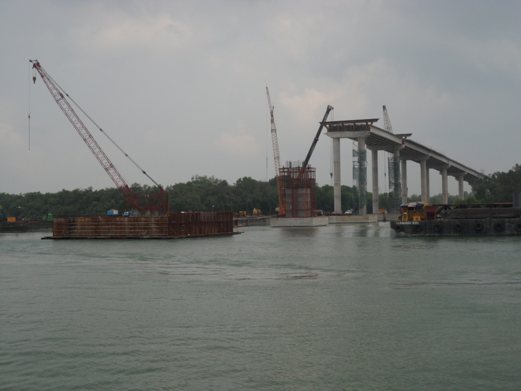
This advantage proved very cost effective on one major bridge construction contract in Tunisia, where the ground conditions consisted of very soft alluvial clays to depths of up to 400 metres.
Our project
used this system for the construction of bridge crossing Lumut Strait at Klang.
The test conducted by Fugro Loadtest Asia Ptd. Ltd. for the 1.6m Ø bored piles with 75.96 m deep
piles under bentonite slurry with sub
surface condition at the test pile location consist primary of silty sand,
sandy clay, silty clay and sandy silt.
The maximum
sustained bi directional load applied to the pile was 7.84MN. at the this load,
the displacements above and below the O-cell assembly were5.12mm and 114.18 mm.
Method Statement of O-cell
Site Sub-surface Condition
The
sub-surface stratigraphy at bore hole BH-2A near the location of the test pile
is reportd to consist of silty sand, sandy clay, Silty clay and sandy silt. .
Test pile Construction
.JPG)
The
1600mm diameter test pile was excavated to
a toe elevation of 72.93m, under bentonite
slurry.

The pile
was started with a a 1650mm O.D casing which was inserted into the sea bed
prior to commencement of drilling.
A reverse circulation drilling was adopted for
drilling the pile.The
bottom of the pile was airlifted after drilling.
After the
pile approved for concrete placemet, the reinforcing cage with attached O-cell
assembly was inserted intothe excavation and tempororary supported from the
piling platform.


Concrete
was then delivered by tremie though a 300mm O.D. pipe into the base of pile
until the top of concrete reached an elevation level of 2.28m.
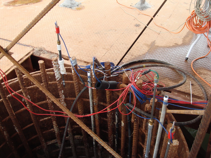
Pile Instrumentation
The
loading assembly consisted of two 405 mm O-cells, locaed 17.54 meter above the
pile toe. The Osterberg cell were calibrated to 6.0MN and then welded closed
prior to shipping by the manufacturer. Calibrations of O-Cell and
instrumentation used for the this test shall submitted to supervision
consultant for review.
Embedded
O-Cell testing instrumentation comprised the following:
·
Two
upper compression telltale casing (nominal 13mm steel pile) attached at 180º
spacing to the reinforcing cage, extending from the top of the O-cell assembly
to the platform level.
·
Two
pile toe displacement telltale casing (nominal 13mm steel pipe ) attached at 180º
spacing to the reinforcement cage, extending frothe bottom of the reinforcing cage
to working platform level.
·
Two
linear vibrating wire displacement transducer (LVWDT’s, Geokon Model 4450
series) positioned between the lower and upper plate of the O-cell assembly.
Details
concerning the instrumentation placement as per Figure A.
Four
length of steel pipe were also installed, extending from the top of the pile to
the top of the bottom plate, to vent the break in the pile formed by the
expansion of the O-cells, The pipes were filled with water prior to the start
of the test
Test
Arrangement
The element
of the pile displacement response were monitored using the equipment and
instrument as below:

·
Top
of pile displacement was monitored using a survey level from a distance of
approximately 4 meters
·
Upper
pile compression was measured using four 8 mm telltale rods positioned indide
the casing and monitored by Linear Vibrating Wire Displacement transducers
(LVWDTs, Geokon model 4450 series attached to the top of pile.
·
Pile
toe displacement was measured using two 8mm teetale rods positioned inside the
casing and monitored by Linear Vibrating Wire Displacement transducers (LVWDTs,
Geokon model 4450 series attached to the top of pile.
Both
pressure gauge and a vibrating wire pressure transducer were used to measure
the pressure applied to the cell at each load interval.
Data Acquisition
All
instrumentation were connected thorough a data logger ( Data Electronic
geolongger 85G) to a laptop computer allowing data to be recorded and stored
automatically at 60 second interval and displayed in real time.

The
O-Cell were loaded in 10 equal increments to a bidirectional gross O-cell load
of 7.84 MN at 1L-10.
The load
increments were applied as specified in the loading schedule presented and
agreed by supervision consultant.
The cycle of load table same as common test
only the result of test based on analysis of recorded data during the test.
The example calculation and theory and also result based on the O-cell Test as below:


 |
However this method still new in Malaysia and the only registered company have the right to do such a test only Fugro Loadtest Ptd Ltd from Singapore. The rate compared with common static load test is reasonable within RM 80/ tonne but it can produce better way in load test for the future.
I'm lucky because have seen by own eye these method. so till we meet again.
mata-ne , sayonara.
I'm lucky because have seen by own eye these method. so till we meet again.
mata-ne , sayonara.
very nice blogs your site is good.have shared useful information ......Thankq for load cell amplifier
BalasPadamload cells
best sharing bro..thnaks.
BalasPadam